| View previous topic :: View next topic |
| Author |
Message |
Frosty555
Trick Member


Joined: 14 Jun 2003
|
0.  Posted: Mon Jan 29, 2007 1:27 pm Post subject: GUIDE: The Correct Way to Light Your Homepad Posted: Mon Jan 29, 2007 1:27 pm Post subject: GUIDE: The Correct Way to Light Your Homepad |
 |
|
I really hope someone finds it in their heart to sticky this, haha
The Correct Way to Light Your Homepad
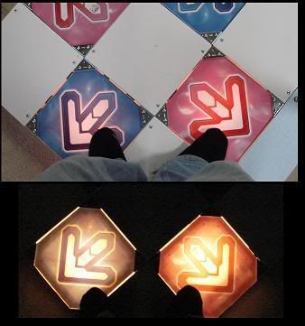
I had a few people asking me how I did the lighting for my girlfriend's birthday pad (here), so I thought I'd make a thread and explain exactly how it works. Maybe some of you up-and-coming ddr pad builders will find this useful 
This guide assumes you have a basic understanding of electronics, you can read simple circuit diagrams, and you already understand the design of the ddr pad you're building.
----------------------------
What You'll Need
- An almost complete home built pad. The pad must have sensors which are, in the end, basically switches (two leads that connect together when you step on the arrows)
- 16 Rectifier Diodes
- Light bulbs or LEDs
- DC Power Adapter
- Optional: Electronic Breadboard for holding all the components in place.
Choosing between LEDs and Lamps
However you decide to light your pad, you have to use a DC source of light. By that I mean that you cannot use a regular 120 volt AC light bulb that you'd screw into your kitchen's overhead light. DC lamps run off of DC power sources like batteries, or power adapters. There are two popular types of DC lighting that you can use in your pad. DC Lamps, or LEDs:
DC Lamps(picture)
Incandescent DC lamps are small light bulbs you can buy from Radio Shack. They run on DC current, *not* AC. They are usually very small bulbs but burn fairly bright. I try and aim for bulbs that say they draw about 250milliamps (0.250 amps) of current.
Mounting a lamp into a pad couldn't be easier. All you need is the right kind of Lamp Base for your lamp. There are two types: Bayonet, and Screw-in, and they are for Bayonet and Screw-in lamps respectively. There isn't any functional difference between the two, but make sure you get the right holder for the right lamp  . .
Type of bases: (screw-in) (bayonet):
LEDs (Picture)
LEDs are bright, focused lights that run on DC current. There's probably a green one on the front of your monitor glowing right now.
LEDs are popular for DDR pad lights because they light instantaniously. A lamp, in contrast, takes 1/10th of a second or so for the wire inside them to start glowing and actually release light. Another reason why LEDs are used is because they require far less power than a typical DC bulb. Where a DC Bulb may draw 250 milliamps, an LED will draw more like 1 milliamp.
LED stands for (L)ight (E)mitting (D)iode. As you'll read later in the guide, diodes only pass electricity in one direction. Therefore you have to take care not to mix up the + and - leads on an LED when you put it in the circuit. LEDs have one leg longer than the other, and the longer leg is the positive one.
LEDs are very focused. You will probably find that if you only use one, your arrow will have a small bright spot of light on it, and not be lit entirely. You will need to arrange several LEDs inside your arrow to light the whole thing.
I have not found an easy way to mount LEDs. LED holders are expensive and I've only found them for sale in packs of 1 or 2, but again I recommend using an LED holder and not trying to make your own make-shift light holder.
AC Light bulbs, neon tubes, any other source of AC lighting
DON'T use any of these methods to light your pad. They are incompatible with my circuit design and there is the possibility of electrocution if you accidentally come in contact with live wires from your wall outlet.
-------------------------------------------
Traditional Wiring Method and their Drawbacks
The traditional way of lighting your pad is to use a "double circuit". The "double circuit" is the simplest way of lighting your DDR Pad, but has some drawbacks. Simply put, you can wire a completely separate sensor and circuit for your lights as you do for your arrow and the two have nothing to do with each other.
Analyzing riptide's pad design, he uses 16 screws laid in a circle inside the arrow well for his sensor. If you were to make a double circuit, you would dedicate half of those screws only for the lights, and the other half for the sensor, or sink additional screws in solely for the lights.
This method is not desirable for two reasons. The first is that it compromises your sensor and makes it less effective. Half the screws means half the sensitivity and accuracy of your arrow. If you're building a DDRHomepad design, you have to split the metal underneith the pad into two parts. If you're using official arcade sensors... well then you're just screwed or you get to buy twice as many sensors  . Secondly, the light is not a true indicator of if your pad is down! Since the lighting sensor is separate from the pad sensor, it is very possible for the light to be on, and the pad is not, or vice versa. The light cannot be used as a way to test or calibrate your pad. . Secondly, the light is not a true indicator of if your pad is down! Since the lighting sensor is separate from the pad sensor, it is very possible for the light to be on, and the pad is not, or vice versa. The light cannot be used as a way to test or calibrate your pad.
The Diode Method of Wiring your Pad
This is my method of lighting the pad. It uses four diodes per arrow to isolate the lights from the playstation controller while still running both lights and pad on the same sensor. This means you design and build one sensor for your ddr pad, and it controls both the playstation button, and the lights.
Diodes are an electrical component which only allows electricity to flow in one direction. They come in a wide range of types, but the one you want is "Rectifier Diode". Radio Shack has them for sale in a 25 pack. You will need at least 16 diodes.
I assume that - whatever sensor design you are using - it eventually simplifies down to a switch. When you push the panel down, the switch closes, otherwise it is open.
The simplest way to make a DDR pad - e.g. one without any lights at all - is to connect this switch directly to the contacts of a playstation controller's button. That way when you close the switch, the playstation button gets activated.
The simplest DDR pad circuit for one arrow would look like this:
| Code: |
PS2 Contacts
---- + - ----
| |
| |
| |
| / |
----/ -------
|
In a perfect world, it would be nice and convenient to connect the *same* switch to a battery and a light, so that when you close the switch, the light would come on, like this:
| Code: |
PS2 Contacts
---- + - ----
| |
| |
| |
| / |
----/ -------
| |
| |
| |
-- + - --- X--
Battery Lamp
|
Of course this wouldn't work. The problem is that the power source for the light would interfere with the playstation controller and vice versa (possibly damaging one or the other).
So the circuit I designed uses four diodes (per arrow) to isolate the ps2 circuit from the lighting circuit, even though they run off the same switch. A diode is a component that only allows current to travel in one direction.
| Code: |
PS2 Contacts
---- + - ----
| |
V ^ ^ - diode (current travelling up )
| | V - diode (current traveling down)
| / |
----/ -------
| |
^ V
| |
-- + - --- X--
Power Lamp
Source
|
Pay attention to the + and - of the playstation and power source. It needs to be exactly how it is in the diagram.
A diode looks like a tiny black cylinder with a line drawn on one end (picture). The side the line on shows the direction that positive current can flow. e.g. current can flow starting from the side the line is not on, through the diode out the side the line is on, but not the other way around. So, in the circuit a bove, "V" would be a diode wit hthe line facing down, and "^" is with the line facing up.
You have to use a diode which can handle the current of your power source. I recommend using 1N400# series diodes. I used 1N4007 diodes, they can handle something like two amps each, enough to handle one hell of a light (considering most kitchen appliances probably run on about that). If you use a diode which can't handle the current of your light, they will get very hot, possibly being a fire hazard (well okay, maybe not a *fire* hazard, but it will get extremely hot, scorch anything it is touching and burn you if you touch it. Then the diode will stop functioning, and your lights will fry your controller  ). ).
Also, keep in mind most diodes have a "breakdown" voltage, e.g. a voltage at which they can no longer stop current from flowing in the wrong direction. You have to keep your power supply lower than this voltage by at least 10% or so. If you use any of the 1N400# diodes you shouldn't have any problem. They all work for anything under 50v, and I can't imagine any reason you'd need lights powered with 50v DC.
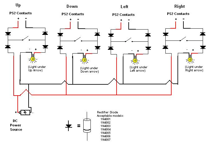
Now, this is all only for one arrow. You need to duplicate this circuit four times (or 5 or 6 if you're doing pump it up or ddr solo). You can connect all of your arrows to their respective playstation contacts, and all of the lights can be connected to the *same* power source. The final (rather messy looking) circuit looks like this:
Where to get your Power
So far the guide has simply talked about your "power source". Your lights need a power source, which, in the above circuit, is shown as a battery.
Batteries can be used in your pad, but they will inevitably die after a while and need replacing. More cost-effective (and simpler) would be to use a DC Adapter. DC Adapters can be purchased in stores, or pulled off an old piece of hardware. They plug into your wall and convert the 120vAC electricity from your wall into DC electricity (anywhere from 2 to 20 volts, depending on the adapter).
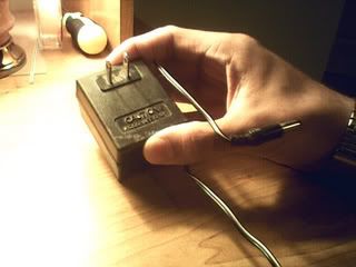
There are two important characteristics to your DC Adapter that you have to make sure of: the voltage rating and the current rating. You can see these if you look at the label on the DC Adapter. Marked "output" will be the voltage and current.
(Picture of a DC Adapter 12v 500mA)
(Picture of an AC Adapter 9v 500mA)
Note how in the AC adapter, the output stated "AC" electricity. This is NOT what you want. This adapter would not be suitable for your lights.
The voltage is the number of volts the adapter will output to your lights. This number is fixed and must be the same (or close) to the voltage your lights are rated for. If you use an adapter that provides too high a voltage, you will blow your lights. Too low and your lights will be dim.
The current is the *maximum* amount of power the adapter is capable of delivering. It is okay to not draw the complete potential of your adapter, but if you draw too much power the adapter will get hot, be unable to provide the voltage it is rated for, and possibly burn out and get damaged. There is a formula near the bottom of this guide that tells you how much power your pad will require. Your adapter must be rated for more or the same amount of power power as your pad will require.
Once you have the power adapter you want to use, cut off the tail of it, separate the two wires (which are most likely connected by a thin piece of insulation) and strip the two wires. Using a volt meter, check and verify which wire is positive and which is negative. Measure the voltage and if it comes out negative, reverse the leads. Once you are reading a positive voltage from the adapter, the red lead is connected to the positive wire and the black lead is connected to the negative wire.
This can be used as your power source and connected to the rest of your lights through those two stripped wires.
(Picture of a stripped adapter ready to be used)
Tips and Thoughts
A few things I encountered along the way that will help you out:
1) Get diodes which can handle the current of your power source. If you get diodes which cannot handle the current, they will get extremely hot. I used mostly 1N4007 diodes because they can take several amps of current.
2) Wire multiple bulbs in parallel if you are putting multiple bulbs underneith a single arrow well (which you probably will be doing if you want it to look good). The bulbs should be connected like this (for one arrow):
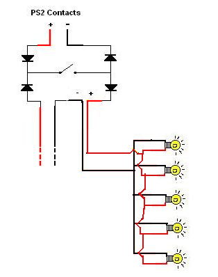
Of course, this picture is for ONE arrow only. You'd repeat this four times for all four arrows. In the above example, it would result in your pad having 20 bulbs (five per arrow).
It is especially important to watch the + and - ends of your LEDs if you decided to use LEDs.
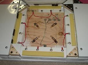
Here's an example of how I wired the inside of my arrow well:
Advanced Light setups (series and parallel combinations)
For those who are a little more experienced around their soldering iron, there may be times when your DC power source doesn't match your lights. There are a few things you can do about that by wiring some of your lights in series, and then sets of those in parallel.
If (under a single arrow well) you connect all the LEDs in parallel, they will all each get the same voltage as your power supply. For every additional LED you put, it will simply draw more power from the adapter. This is the simplest and most intuitive way of connecting lights and I just described it above in point 2.
If, however, you instead were to connect your LEDs in series, they will divide the voltage evenly amongst themselves, and draw the same amount of current as one light. Of course, lower voltage = less light output so you'll discover three lights in series each shine about 1/3 as bright as one.
This is useful if you have an adapter that has too high a voltage rating. As an example, lets say you have a 9v DC adapter capable of 500mA of current, and LEDs that required 3 volts and used 100mA each.
Putting the two together, you could connect three LEDs in series, so each would draw 3v and the set as a whole would only draw 100mA. Then, connect three "sets" of these together in parallel. The result is nine LEDs, each getting 3v and the entire thing consuming 300mA.
One entire arrow down would then draw 300mA, two arrows down draw 600mA, and three arrows would draw 900mA.
I'll try and draw series vs. parallel with my makeshift ascii art  : :
| Code: |
--O-- LED (+'ve lead to the left)
Lights in Series (each light gets 1/3 the voltage)
+ ----O---O---O-
|
- --------------
Lights in Parallel (each light demands more power from the power source)
----O----
| |
|----O----|
| |
|----O----|
| |
| |
+ -
|
So, that's one thing you can try if you have a power adapter that provides *too* much voltage. It's a nice trick to lower your total power requirements as well. My personal setup was a 14v 2000mA adapter connected to four bulbs (two in series, and two sets of those in parallel). Each light was rated at 6v and 250mA. My adapter ended up giving them about 7v each. Each arrow, then, drew 500mA, and the four arrows all together had the ability to draw a maximum of 2 amps. Worked out perfect.
4) How to calculate your maximum power consumption. Since your power source must be capable of delivering at least this much power, a good estimate for knowing how much power you will need is to do this:
[current one bulb requires] X [number of bulbs under one arrow] X 2.
This assumes you connected all your bulbs in parallel like in the above diagram. If you did the advanced lighting described above, you'll have to do those calculations to figure out the power consumption. As an example: if you have four light bulbs in parallel under one arrow, and each bulb draws 100mA, your power source should be capable of 100ma x 4 x 2 = 800 mA.
The reason why I do x2 is because most of the time only two arrows will actually be lit at once. If you were to perform a quad hold, your pad may draw as much as 1600mA for a short period of time, but in my opinion, it is negligible since the lights would not be on for long.
5) Use a breadboard for your diodes. It makes things far less messy when you are soldering. This is what my final circuit looked like:
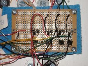
You can see how the four pieces to the circuit are layed out on horizontally across the board. You don't have to do it this way of course, you could lay out each part of the circuit underneith its respective arrow well, but I only felt like buying one breadboard instead of four  . Those things are like $5 each you know! . Those things are like $5 each you know!  . .
----------------------------------------------------------------------------
Revisions
Jan 30 2006 - Added some more info on DC lamps and lamp bases
Jan 31 2006 - Added info on power adapters. Needs pictures. Fixed circuit diagram bug.
_________________
Last edited by Frosty555 on Wed Feb 21, 2007 8:02 pm, edited 17 times in total |
|
| Back to top |
|
 |
Edible Bondage Tape
Trick Member


Joined: 26 Jan 2002
Location: Kerri |
1.  Posted: Mon Jan 29, 2007 1:39 pm Post subject: Re: GUIDE: The Correct Way to Light Your Homepad Posted: Mon Jan 29, 2007 1:39 pm Post subject: Re: GUIDE: The Correct Way to Light Your Homepad |
 |
|
| Frosty555 wrote: | . LEDs have one leg longer than the other, and the longer leg is the positive one.
|
this is only a defacto standard NOT an industry standard so read the spec sheet (or better yet put it in a tester) before you put them in
_________________
|
|
| Back to top |
|
 |
Frosty555
Trick Member


Joined: 14 Jun 2003
|
2.  Posted: Mon Jan 29, 2007 2:24 pm Post subject: Posted: Mon Jan 29, 2007 2:24 pm Post subject: |
 |
|
Good point. (and sometimes the legs are disfigured and you can't tell anyhow). I didn't want to overcomplicate things but it is always a good idea to *test* the polarity with a meter or a battery just so that you're certain you got it right.
_________________
|
|
| Back to top |
|
 |
pui-puni
Basic Member


Joined: 15 Dec 2004
Location: Montreal |
|
| Back to top |
|
 |
LightningXCE
Trick Member

Joined: 17 Aug 2006
|
4.  Posted: Mon Jan 29, 2007 3:57 pm Post subject: Posted: Mon Jan 29, 2007 3:57 pm Post subject: |
 |
|
=D
Same ASCII as that PM, I see.
Another way that you can tell which "leg" is which on LED's are the little notch on the top. You'll see a flat side of the base of the LED that detonates which side is Cathode. The other, obviously, is Anode.
Thanks again for this, it helped greatly with my setup!
_________________
=o! |
|
| Back to top |
|
 |
Edible Bondage Tape
Trick Member


Joined: 26 Jan 2002
Location: Kerri |
5.  Posted: Mon Jan 29, 2007 5:05 pm Post subject: Posted: Mon Jan 29, 2007 5:05 pm Post subject: |
 |
|
and for those who dont know cathode is negative
_________________
|
|
| Back to top |
|
 |
ChilliumBromide
Trick Member


Joined: 16 Jun 2006
Location: Beaverton, OR |
|
| Back to top |
|
 |
Discoman
Maniac Member

Joined: 23 Nov 2002
|
7.  Posted: Mon Jan 29, 2007 9:03 pm Post subject: Posted: Mon Jan 29, 2007 9:03 pm Post subject: |
 |
|
| Ok, since there's been a big hubbub of lighting issues lately and people making their own threads, this one will be stickied on a trial basis (as it has some meaty info) for discussion and questions and adding of information to the topic and discouraging folk from making topic after topic about lighting. However, there may be a point where compilation of information such as this and lexan/acrylic comparison, etc will need to be merged into one thread. |
|
| Back to top |
|
 |
Frosty555
Trick Member


Joined: 14 Jun 2003
|
8.  Posted: Tue Jan 30, 2007 8:15 am Post subject: Posted: Tue Jan 30, 2007 8:15 am Post subject: |
 |
|
Hooray! Thanks for the sticky 
| LightningXCE wrote: | | Same ASCII as that PM, I see. |
Yep  the pm i sent you made the basis for most of this thread, haha XD the pm i sent you made the basis for most of this thread, haha XD
I can post some pictures of how to use a DC adapter. I ended up doing that too, I used an adapter from an old printer I had. Essentially, you find a DC adapter with enough voltage/current output, and chop off the smaller circular plug, strip the wires, and presto - unlimited DC power so far as the adapter is capable of.
I totally agree batteries suck but I didn't want to imply any where that anyone should try and use AC power directly from their wall. XD I'd hate for someone to get electrocuted trying to get that to work x_x
_________________
|
|
| Back to top |
|
 |
ChilliumBromide
Trick Member


Joined: 16 Jun 2006
Location: Beaverton, OR |
|
| Back to top |
|
 |
Frosty555
Trick Member


Joined: 14 Jun 2003
|
10.  Posted: Tue Jan 30, 2007 9:04 pm Post subject: Posted: Tue Jan 30, 2007 9:04 pm Post subject: |
 |
|
It allll depends on the lights my friend, however there are a few things you can do.
If (under a single arrow well) you connect all the LEDs in parallel, they will all each get the same voltage as your power supply. For every additional LED you put, it will simply draw more power from the adapter. This is the simplest and most intuitive way of connecting lights so I put it like that in the guide.
If, however, you instead were to connect your LEDs in series, they will divide the voltage evenly amongst themselves, and draw the same amount of current as one light. Of course, lower voltage = less light output so you'll discover three lights in series each shine about 1/3 as bright as one.
This is useful if you have an adapter that has too high a voltage rating.. Lets say you have a 9v DC adapter capable of 500mA of current, and LEDs that required 3 volts and used 100mA each.
You could connect three LEDs in series, so each would draw 3v and the set as a whole would only draw 100mA. Then, connect three "sets" of these together in parallel. The result is nine LEDs, each getting 3v and the entire thing consuming 300mA.
One arrow down would then draw 300mA, two arrows draw 600mA, and three draw 900mA.
I'll try and draw series vs. parallel with my makeshift ascii art  : :
| Code: |
--O-- LED (+'ve lead to the left)
Series
+ ----O---O---O-
|
- --------------
Parallel
----O----
| |
|----O----|
| |
|----O----|
| |
| |
+ -
|
So, that's one thing you can try if you have a power adapter that provides *too* much voltage. It's a nice trick to lower your total power requirements as well. My personal setup was a 14v 2000mA adapter connected to four bulbs (two in series, and two sets of those in parallel). Each light was rated at 6v and 250mA. My adapter ended up giving them about 7v each. Each arrow, then, drew 500mA, and the four arrows all together had the ability to draw a maximum of 2 amps. Worked out perfect.
-- edit --
Oh yeah, and if you happen to have a couple of the same power adapter (same voltage/current ratings), you can connect the *power sources* in parallel and the total capacity of your power source will be the sum of the two. It gets messy if the current or voltages differ, so I'd only recommend doing it with two identical adapters. Then you could put an extension cord inside the pad and house the adapters in there, running the extension cord out of the pad to the wall.
_________________
|
|
| Back to top |
|
 |
Frosty555
Trick Member


Joined: 14 Jun 2003
|
11.  Posted: Wed Jan 31, 2007 3:55 pm Post subject: Posted: Wed Jan 31, 2007 3:55 pm Post subject: |
 |
|
I edited the guide and posted a section on DC adapters as well as some pictures that would be useful.
_________________
|
|
| Back to top |
|
 |
ChilliumBromide
Trick Member


Joined: 16 Jun 2006
Location: Beaverton, OR |
12.  Posted: Wed Jan 31, 2007 9:51 pm Post subject: Posted: Wed Jan 31, 2007 9:51 pm Post subject: |
 |
|
Well, what I'm looking to do is build a full stepmania cabinet, with a power strip built into it to power the pad, screen, speakers, computer, and cab lights.
And, of course, DTG's customers will probably appreciate having proper lighting for their pads. xD
One more (hopefully last) question though:
How would you make it work on either batteries or DC adaptor?
_________________
I used to be active here lol |
|
| Back to top |
|
 |
Edible Bondage Tape
Trick Member


Joined: 26 Jan 2002
Location: Kerri |
13.  Posted: Thu Feb 01, 2007 8:51 am Post subject: Posted: Thu Feb 01, 2007 8:51 am Post subject: |
 |
|
| DancingTofu wrote: |
You wouldn't happen to know how to hook it up to a power outlet via DC adapter, would you? ;P
|
make a full wave bridge rectifyer you just need some wire a small peice of solid iron (to make a transformer) and 4 diodes (to handel rectification and noise filtering) boom badda bing AC becomes DC
_________________
|
|
| Back to top |
|
 |
Ghettobarney
Trick Member

Joined: 21 Dec 2006
Location: Failing Pandy |
|
| Back to top |
|
 |
Frosty555
Trick Member


Joined: 14 Jun 2003
|
15.  Posted: Sun Feb 04, 2007 12:05 pm Post subject: Posted: Sun Feb 04, 2007 12:05 pm Post subject: |
 |
|
Haha, well, I'm certainly no bar expert. That bar I put on my pad was my first time ever doing it.
I'm sure that the lights come in color. I know for sure that LEDs come in every color imaginable, though red, green and blue (-- edit -- and White, oh yeah. haha, ha) are probably the most common.
Ooh, for the DC Adapter vs. Batteries thing DancingTofu posted... my suggestion if you want to keep it simple is just put a double-throw switch somewhere convenient. Have the pad's +ve lead go to the common pin, and the +ve leads of the Battery and the DC Adapter respectively go to the left and right pin respectively. Throw it left and it is running on batteries, throw it the other way and it is running on the DC adapter.
But if you want to get fancy, you can use a single-poll-double-throw DC relay (named SPDT Relay). A relay is a device that is a tiny switch placed close to a wire coil. When you run current through the coil, the switch is closed by the magnetic field generated by the coil. When current stops flowing through the coil, the switch opens.
Connecting your DC adapter to the coil will cause the switch to be closed any time the DC adapter is plugged in. So you make it so that side of the switch connects the DC adapter to the rest of your lights. Otherwise, the switch is in the open position and the battery is connected to your lights. Basically, it's that same switch you'd use, except it throws itself automatically  . .
The downside to this, is that the relay constantly needs power from the DC Adapter, so whether the pad is in use or not, you will be constantly using a small amount of power (in the ballpark of 10-30mA) just for the relay at all times.
I made a circuit, but I never tested it. I think it'd look something like this:
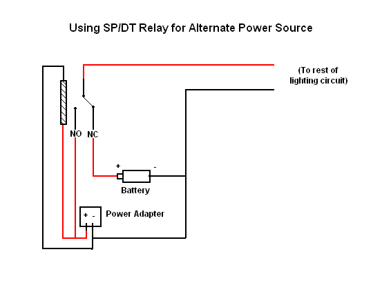
Where that stripy bar is the relay's coil, and the switch right beside the bar is the NO (normally open) and NC (normally closed) leads on the relay.
_________________
Last edited by Frosty555 on Tue Feb 06, 2007 11:17 am, edited 1 time in total |
|
| Back to top |
|
 |
ChilliumBromide
Trick Member


Joined: 16 Jun 2006
Location: Beaverton, OR |
16.  Posted: Sun Feb 04, 2007 10:13 pm Post subject: Posted: Sun Feb 04, 2007 10:13 pm Post subject: |
 |
|
I think I'll just use manual switches; I generally try to believe that DDR players aren't quite as lazy as most gamers, and can flip their own damned switches. ;D
_________________
I used to be active here lol |
|
| Back to top |
|
 |
Frosty555
Trick Member


Joined: 14 Jun 2003
|
17.  Posted: Tue Feb 06, 2007 11:13 am Post subject: Posted: Tue Feb 06, 2007 11:13 am Post subject: |
 |
|
Okay, in that case just take the coil out of that diagram and the circuit still applies. I think just about any switch will do fine for you provided it is double-throw. I think even regular household light switches will work perfect. They're quite heavy duty which I think you probably want if you're selling pads commercially.
_________________
|
|
| Back to top |
|
 |
ChilliumBromide
Trick Member


Joined: 16 Jun 2006
Location: Beaverton, OR |
|
| Back to top |
|
 |
daikenkai =[
Trick Member

![]()
Joined: 01 Oct 2006
Location: 6:51AM getting Diet Pepsi max for keep wake up |
19.  Posted: Sun Feb 18, 2007 7:26 pm Post subject: Posted: Sun Feb 18, 2007 7:26 pm Post subject: |
 |
|
| ive gotta try that! |
|
| Back to top |
|
 |
|
|
You cannot post new topics in this forum
You cannot reply to topics in this forum
You cannot edit your posts in this forum
You cannot delete your posts in this forum
You cannot vote in polls in this forum
|
Powered by phpBB 2 © 2001, 2002 phpBB Group
|





 :
:

 .
.


 I love my pad! <3
 <3 <3 <3


